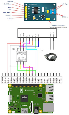
It's finally time to connect some hardware!
So I realised I don't have (can't find) a big enough breadboard to put my Pi breakout board on - I'll have to grab one in the coming days.
Anyhow, I've drawn up a simple diagram about how the Raspberry Pi should be connected to an inexpensive MCP2515 + TJA1050 board. It's really important to use a logic level converter to change the voltage between 3.3v (Raspberry Pi) and 5v (MCP2515 + TJA1050).
While the Pi does output 5v on a couple of it's pins, it's GPIO (general purpose input/output) pins - including the SPI pins, can only handle 3.3v. You risk killing your Pi if you don't use a converter.
The image of the Raspberry Pi is a Pi 3, I'm using a Pi 4. It should be compatible with most Pis that have the standard 40 pin pinout.
The bi-directional logic level converter that I'm using is an old 2 channel LLC. The same wiring configuration should work with newer 4 channel LLCs.
Now that all of that is connected, it's time to log into our Pi using SSH (as per the last post) and make some small changes.
- in /boot/config.txt, add the following text to enable mcp2515 support:
dtoverlay=mcp2515-can0,oscillator=16000000,interrupt=25,spimaxfrequency=16000000
Note: 16000000 (16mhz) is exactly double my clock speed (8 mhz), update to match your clock (that little silver thing) on your MCP2515 + TJA1050 board.

Comments
Post a Comment